How to Install and Tune an AVC-R Boost Controller
By Azeem Raja
After playing with my AVC-R for a couple of weeks I think I have figured it
out... at least well enough to provide some help with installation and tuning.
** Standard disclaimers apply. Please be careful, you can easily pop your motor with this thing! I assume no responsibility for anything**
INSTALLATION
Installing the unit will take 3-6 hours, depending on how mechanically and
electronically inclined you are. The single most time-consuming step is splicing
into the ECU wires. The supplied installation instructions aren't bad, follow
the FD specific instructions EXACTLY.
Also, you should review the boost controller installation info on Steve Cirian's
and Rob Robinette's sites... the principals of installing any EBC are very
similar to installing this unit, and the pictures on Rob's site are very
helpful.
STEP 1) Install the Solenoid
The solenoid controls the air pressure provided to the precontrol and
wastegate actuators, thus allowing user control of boost. If you blow through
the solenoid (NO or COM port) you will feel a little resistance, but air will
flow. If air doesn't flow there is probably a problem. (So loss of power to the
solenoid will result in low boost, not max boost...)
· Remove air box and intake piping so that you can access the precontrol and WG
actuators (look almost straight down).
· Remove both of the hoses going from the manifold to Precontrol & WG
actuators - hoses are held on by expandable metal clips * Following the
directions, use the supplied plastic 'T's and hoses, and 'T' the manifold ports
to the NO port on solenoid.
· 'T' the Precontrol & WG actuator ports to the COM port on solenoid.
· Mount the solenoid - use the rubber pad. Mine is mounted on the fender wall
near the ABS unit.
STEP 2) Disconnect factory solenoids
This MUST be done, otherwise boost cannot be controlled.
· There are two ports each on the wastegate & precontrol actuators.
The top port from each is running to the solenoid (step above), the second port
is at the bottom and to the right... you cant see it, but it's easy to feel.
· Disconnect bottom ports on each
· Plug both these ports (i.e. rubber stopper and tie wrap)
· Plug both hoses that were connected to the ports
STEP 3) Install pressure sensor
Pressure sensor monitors manifold pressure to provide 'closed-loop' boost
control.
· Find a hose on intake manifold and 'T' it to the pressure sensor.
· Use the supplied air filter and mount the sensor so the hose connector points
downward.
· On my car there were two threaded holes on the fender-wall, close to the
firewall, next to the ABS. The pressure sensor mounted there PERFECTLY (supply
your own machine screws).
STEP 4) Wiring harness
· Start with harness inside the car and run the solenoid and pressure
sensor wires into the engine compartment.
· You do not need to cut the wires, the wire 'ends' can be removed from the
plastic connector using a small screwdriver (pop out plastic insert.)
· Hole in firewall behind/under ABS and behind glove-box works well.
· Follow the supplied FD ECU wiring diagram (Z3-b) and spice into required ECU
wires. I used 'RPM' wiring, not 'injector duty' wiring.
· Attach all sensor and head-unit connectors
STEP 5) Sensor Check
· Put everything back together (at least enough to turn ignition on).
· Turn ignition on (don't need to start the car yet)
· AVC-R logo will scroll across the screen
· Go to 'Etc.' section, 'Sensor chk'
· My values:
Boost: 1.513V
Throttle: 0.634V (no throttle) / 4.218V (full throttle)
SCSW: OFF
· If your values are close, the unit and sensors are working.
· Put everything back together - enough to drive car. Complete system
checkout is in next section.
TUNING
Basic tuning will take a few hours, but fine tuning all the parameter will
take a while. The tuning instructions in the manual leave a lot to be desired...
the translation is fairly poor. Read and re-read this section, about the third
time you read it, it does start making sense. And if it seems that a word is
missing in a sentence... it IS! I guess the translator didnt know the English
word. So I attempt to explain what each of the parameters does along with how to
set it.
Also, the boost is displayed in Kg/cm^2... the conversion to PSI is 14.22:1 NOT
14.5 or 14.7 or anything else.
STEP 1) System parameter setup - All in 'Etc.' menu
Car Select:
Cyl=4 (# of rotors * 2)
Spd=4
Thr=Arrow pointing up
Sensor Sel:
Relative1 (leave as default)
Gear judge:
This is how the unit knows what gear you are in. Set as follows:
1st 5
2nd0
3rd 9
4th 5
5th 5
Read directions to check, but these should be very close for all FDs.
Grph Scale:
These are units for the graphing view modes only.
Bs=1.0kg/cm^2
Ne€00rpm
Sp 0km/h (good to 112mph)
STEP 2) Mode [A] setup
Boost/Duty
Values which control boost
Set boost at 0.65 (can be anything, but 9psi seems like a safe start)
Set duty cycle at 25%
Scramble:
I did not use this feature
Ne-Point
These are the RPM points at which boost/duty cycle can be individually set -
RPM's less than the lowest point use the settings for the lowest point, same for
higher than highest point.(It works...)
I use: 3000,3500,4000,4500,5000,5500,6000,6500
F/B speed
This is the 'boost control sampling frequency' - i.e. how often the
controller checks the boost and corrects it. The basic idea is, if boost
consistently overshoots, increase number; if boost oscillates, decrease number.
However, I found no perceptible difference in boost pattern, no matter what I
set this value to. I used 'start-duty' (described below) to control initial
boost spiking.
So leave at default setting of 3 for all gears
Learn-gear
This turns 'self-learn' mode on/off, per gear. With this turned on, I found
that the unit kept dialing my transition spike back IN (eliminating spike is
later). I turned learn-mode OFF in all gear, this is 'X' for all gears. But
learn mode may work better in your car... experiment with it.
Start-Duty
This controls initial spiking - i.e. quick no-throttle to full-throttle at
3K. This feature reduces the max boost a little, when going from negative
pressure to boost... so it has the desired affect of reducing the initial spike,
but not impacting sustained boost. Controlling initial spike is covered later,
for now if can be set to 0% for all gears.
STEP 3) Learn to navigate through display & setup screens
If you have not done so already, play with all the display modes, moving
around with [prev] & [next], etc. I found that the most useful display mode
for tuning was 1-channel, displaying boost, then hit [up] to display a peak-hold
value, hit [right] to reset this value, as needed. 2-Channel w/Boost & RPM
is also a good mode. Also, hit [prev] & [next] at the same time, to jump
between the 'last' display screen and 'last' programming screen - very useful!
STEP 4) Complete system checkout
· Start Car
· RPMs displayed on unit should match tach exactly
· Boost on unit should be close to your analog boost gauge (mine match
exactly).
Let the car warm up and then go for a drive... I think the ECU can no longer
put the car into 'limp-home' mode, so you need to be extra-careful driving
around on a cold engine.
· With unit [off] carefully apply power. You should develop 7psi max (0.5
Kgcm). My boost pattern is 7-5-7, dip to 5 before transition and then back to 7
to redline. If there is a problem with the install, i.e. if you didn't
disconnect the factory solenoids, the boost may spike above safe levels! I got
16-17psi at 2600rpm. If so recheck everything.
· Turn the unit to setting [A] and again carefully apply power (you may
hear the solenoid clicking - that's good), but stay below the 4500rpm for now.
You should get close to 9psi... if not, increase the duty cycle a little (1-2%),
retest, keep increasing until you get to 9psi. If you set the duty cycle too
high, the controller will not be able to control boost, and will run higher than
9psi. For 9psi the duty cycle should be around 30%-40%. If the boost is not
going above 7psi, there is a problem with the install. Recheck everything.
· If all this works, basic controller functions are working.
STEP 5) Fine tuning boost curve
For the tests above, a 'constant/flat' boost and duty cycle curve were set.
However, pressing 'next' from the boost and duty cycle allows you to set boost
and duty cycle per 500rpm increments.
· Setting 1st turbo boost
As done in the test above, set the boost you want to run (per 500rpm as
desired). Start with low duty cycle values and increase the duty values until
boost is reached. Increase the values SLOWLY, i.e. 1-2%, and retest. Also, pick
the lowest value that holds desired boost... +/- 5% will still hold boost, but
the higher the value, the higher the initial spike at that RPM.
· Controlling the transition spike
There are a couple of different ways to dial-out the transition spike. Exactly
which method works best depends on your car's setup and the boost level you want
to run. Basically, the transition spike is controlled by reducing the duty cycle
and/or boost level at 4000 and/or 4500. It may take a small reduction of duty
cycle, i.e. 5-10%. If this doesn't work, you may need to greatly reduce the duty
cycle, i.e. all the way down to 20-30%. If this doesn't work, you may need to
reduce the boost level at 4000 and/or 4500 by 0.05 or 0.1 Kgcm - this should
definitely take care of the spike. I had to reduce my boost, but most everyone
else I talked to only need to reduce duty cycle. Dialing out the spike perfectly
takes a LOT of time...
· Setting 2nd turbo boost
This is done the same way as the 1st turbo, except adjust duty cycle / boost
level from 5000rpm on up.
· Controlling initial boost spiking
I found that a couple of % reduction of duty cycle eliminates any overshoot.
I am running:
1st= 0%
2nd= 0%
3rd= 0%
4th= -1%
5th= -3%
· My boost/duty cycle curve (12psi)
3000: 0.85 / 53% (same for 1500, 2000, 2500)
3500: 0.85 / 53%
4000: 0.80 / 45%
4500: 0.75 / 40%
5000: 0.85 / 50%
5500: 0.85 / 55%
6000: 0.85 / 55%
6500: 0.85 / 55% (same for 7000, 7500, 8000)
STEP 6) Mode [B] setup
Repeat all the fun you just had with Mode [B]!
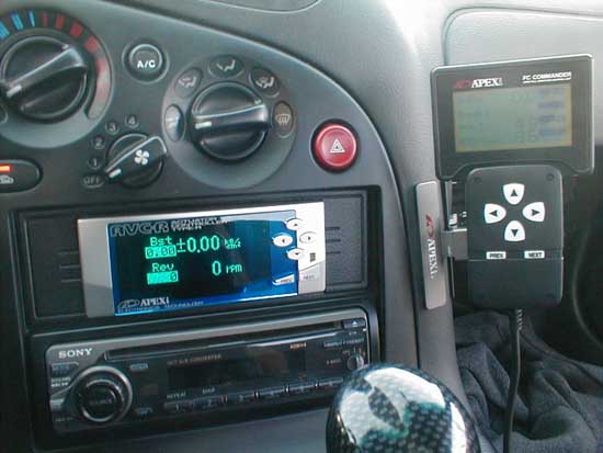
MOUNT 'HEAD' UNIT
You're on your own for mounting... Steve's site has some info on this
(Rick's post). I have a touring model, and ended up removing my CD-player,
getting an R1 console "pocket" and mounting it in the pocket. If you
want to do this, two words: Dremel Tool. Sections of the top and bottom of
pocket must be removed, but the dash does not need to be touched, and the pocket
door and spring mechanism work fine. It looks pretty good when complete.
That's everything I can think of...
Good luck,
Azeem
|