RX-7 Boost Control
By Rob Robinette with contributions by Kevin Kelleher & Max Cooper
![]() < Convert this web page to Palm Pilot Doc format
< Convert this web page to Palm Pilot Doc format
How the Stock RX-7 Boost Controller Works
The 3rd gen RX-7 uses an "open loop," non-feedback boost controller. The wastegate, which diverts exhaust away from the turbos, is controlled by a combination of air pressure and the engine's ECU. Air pressure in the wastegate actuator opens the wastegate. The higher the pressure the more the wastegate opens. Airflow "in" to the wastegate actuator comes from the turbos themselves and is reduced by a restrictor pill in the vacuum line between the primary turbo and the wastegate actuator. Airflow "out" of the wastegate actuator is regulated by a solenoid that is rapidly cycled open and closed at a rate dictated by maps in the ECU.
Air pressure in the wastegate actuator controls the wastegate which varies boost. The more pressure the actuator sees the more the wastegate opens and the more boost is lowered. The wastegate actuator has a mechanical spring that holds the wastegate closed until approximately 7 psi of boost is achieved. The stock boost pressure of 10 psi is factory set with the restrictor pill. A smaller opening in the pill will reduce air pressure and raise boost.
Although the ECU controls the wastegate control solenoid, it does not use boost pressure feedback to vary the amount of air pressure vented out of the wastegate actuator (open loop). The ECU blindly opens and closes the wastegate control solenoid at different rates depending upon rpm, throttle position and other factors (this is mapped in the ECU's firmware). When the ECU goes into the "limp home mode", it holds the solenoid closed which allows a spring limited 7 psi of maximum boost. See the Turbocharger Cutaway for more information.
Boost level can be manually controlled by replacing the restrictor pill with a manual bleed valve. See the Manual Boost Controller how-to.
How the Secondary Turbo is Pre-Spooled
How After-Market Boost Controllers Work
After-market electronic boost controllers such as the GReddy PRofec and HKS EVC (Electronic Valve Controller) are spliced into the vacuum line taking the place of the boost restrictor pill (see diagram below). They regulate boost by controlling the air pressure in the wastegate actuator. The wastegate actuator's outflow nipple is plugged and all air coming into and out of the wastegate actuator is controlled by the PRofec or EVC. The PFS Powertrain Management Computer (PMC) does not have a separate boost controller. It works through the ECU to control the wastegate control solenoid to raise and lower boost. A reprogrammed ECU (chip upgrade) by Mostly Mazda and others does not control boost, the ECU's fuel maps are simply richened to supply the correct amount of fuel for higher boost. See the PRofec & EVC Boost Controller Install how-to.
Note: On newer cars and turbos the restrictor pill may be replaced by a restricted vacuum line nipple on the primary turbo. If that is the case then you will need to "drill out" the nipple to reduce restriction. If you don't reduce the restriction you will not be able to lower boost below your current level.
RX-7 Boost Control in Action (stock system)
By Rob Robinette
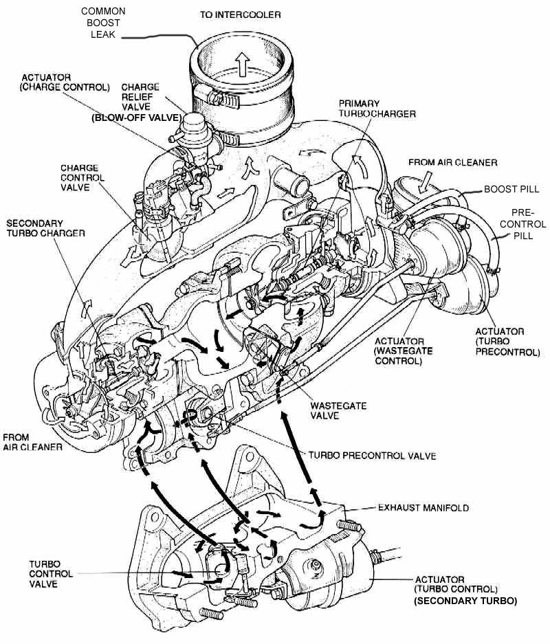
Description of Boost Controls
Wastegate - in exhaust manifold, diverts exhaust away from turbochargers to reduce boost
Precontrol Valve - in turbo manifold, similar to the wastegate, opens to send some exhaust to the secondary (rear) turbo to spin it up before it comes online to deliver boost
Turbo Control Valve - in exhaust manifold, the primary source of exhaust to the secondary turbo
Charge Control Valve - in Y-pipe, isolates the secondary turbo until it is ready to supply boost
Charge Relief Valve - connected to Y-pipe, bleeds off the boost created by the secondary turbo while it is isolated by the charge control valve; this valve looks exactly like the air bypass valve (stock blow-off valve) and is sometimes referred to as the "other blow-off valve"
Air Bypass Valve - connected to the Y-pipe, the stock "blow-off" valve, relieves boost pressure when the throttle is closed while under boost, keeps pressure wave from smashing into the turbos and helps keep the turbos spinning during gear shifts (while throttle is at idle)
See the Turbocharger Cutaway and Vacuum Hose Diagram to help visualize this process.
Boost Control During Low Power
Wastegate closed
Primary (front) turbo spinning but no boost
Precontrol, charge control, turbo control valves closed
Charge relief valve open
Secondary (rear) turbo not spinning
High Power < 4500 RPM
Primary turbo spins up and creates boost
Wastegate opens to prevent over-boost
Precontrol valve begins to open to spin up the secondary turbo
Turbo control valve closed
Charge control valve in Y-pipe is closed, preventing secondary turbo from
supplying boost
Charge relief valve is open, venting boost created by secondary turbo
High Power > 4500 RPM
Primary turbo creating boost
Wastegate open to prevent over-boost, wastegate can be overwhelmed on highly
modified cars causing boost creep
Precontrol valve full open
Turbo control valve opens to supply secondary turbo with maximum exhaust
Charge relief valve closes - stops venting secondary turbo's boost
Charge control valve in Y-pipe opens to allow secondary turbo boost into Y-pipe creating a momentary boost spike
High Power to Low Power Transition
Throttle butterflies rapidly close
Boost pressure in extension manifold drops immediately (this is what your boost
gauge sees)
Boost pressure on turbo side of throttle butterflies spikes
Air bypass valve (blow-off valve) senses vacuum in extension manifold and high
pressure in the Y-pipe so it opens to bleed off the high pressure
Kevin Kelleher Adds:
STOCK CONTROL
The following 4 notes are the result of testing, not my less appreciated theoretical type stuff. Some of that sneaks in later.
1) In primary mode [primary turbo making boost], the wastegate control solenoid duty cycle is fixed at a high percent open [wastegate mostly closed for higher boost]. Average voltage was 11.5 volts. This, with the exhaust dumping at the precontrol, limits the boost.
2) After twin [turbo] mode kicks in at 4500 at WOT, the duty cycle changes to a more closed condition (4-5 volts), less than half the previous value, and stays about there to redline [wastegate mostly open]. This creates lower general boost pressure above 4500 in twin mode, due to less wastegate solenoid venting, causing less pressure drop across the pill, and more pressure proportionally held in the actuator. This also compensates for no exhaust dumping help from the precontrol anymore.
3) If in the previous case you lift at about 4800 rpm, the wastegate solenoid closes for no venting. Floor it again and it jumps to 6 volts, dropping down gradually to 4-5 at high rpm.
4) If you start at low rpm, and ease thru 5000 rpm, voltage stays at 11.5 (max vent). If you ease up past 5500, wastegate solenoid voltage drops to zero, fully closed. (the manual implies twin mode will kick in over 5500 rpm with lite load history.) Now, if rpm are brought back down to 3700, the wastegate solenoid stays closed. Now floor it and solenoid jumps to about 8 volts, and boost slowly rises, clearly locked in twin mode below 4500 rpm. As you continue up at WOT, voltage drops gradually as before to 4-5 at 7000. The 'locked in twin mode' at low rpm is released by a time factor, or by dropping below about 3300 rpm.
There are other interesting traits, but these paint the picture pretty well. My conclusion, based on the smooth, repeatable ramping of the duty cycle in twin mode, is that a complex set of maps based on various inputs, are used to passively control boost in an open loop mode. I like the low rpm boost kick that generally results. The 'max boost cut-out vs rpm' table on Steve Cirian's great site suggests the general boost profile that was desired by Mazda.
AFTER MODS
After heavy mods, I and others found boost (and spiking) was generally up.
This is due to increased vol-efficiency, and higher hp and exhaust flow at the
same old boost levels/conditions.
I said the WG flap cracks open at 8 psi. It is about 1/8 inch open (at the edge
away from the pivot) at 10 psi, and is opened a max of ½ inch at 15 psi. It is
likely that max dump capacity occurs at much less than ½ inch open, limited by
port size. This data was taken off my OEM working system. (Max open was about a
20 degree swing of the WG valve.)
Where before mods, 10 psi at a certain rpm/condition was a result of sol-valve
venting to create mabe 9 psi in the actuator, now that amount of opening of the
WG is not enough dumping of exhaust gas to keep boost pressure from rising
higher. So boost rises more to say 12 psi, and now the actuator pressure is 10
and the wg is 1/8 inch open instead of 1/16 inch for the stock condition, and
boost sabilizes at the new higher pressure. Venting duty cycle maps for the
sol-valve are the same as before mods.
Larger orifices can recapture stock boost levels and control spikes. But w/o an
ECU upgrade, the increased volumetric efficiency with full intake-exhaust-IC
leans out the mixture, and ECU upgrades are needed, unless O2 readings can
confirm adequate mixture. Each car is a bit different in this area.
PRECONTROL Note
Although some state primary boost is only controlled by the precontrol WG, my testing suggested it works in parallel with the main WG to control primary boost. PLEASE, someone with a stock set-up, plug the line to the WG solenoid valve, and see if primary boost drops (this would reassure me, and be proof for doubters). Mine did, but I tested my car with heavy mods. This test is safe.
Kevin Kelleher
How to Adjust the Turbo Precontrol Actuator Rod
John Levy Adds:
<Reprinted from The Drew Files>
Cam Worth of Pettit taught me this procedure in order to eliminate reduced boost on the primary turbo. Apparently, the precontrol door can be open a crack, allowing pressure to divert to the secondary turbo. This adjustment ensures the precontrol actuator rod is pulling the precontrol valve completely closed.
In order to properly set the length of the turbo precontrol actuator rod remove the E-clip that fixes it to the door. Hold (pull) the door arm so that the door is completely closed. Adjust the length of the actuator rod so that the hole that fits over the pin reveals only half of the pin. When you have accomplished this you will have to use a small vicegrip or similar tool to get some leverage on the rod to pull enough of it out of the actuator in order to place the rod's hole over the arm's pin.
John Levy